- Home
- Works & Tech
- Can You Practice Excavation on the Site You Scanned? How to Bring 3DGS into a Construction Machinery Simulator, and What Remains
Tech Articles3DCGSimulation
Can You Practice Excavation on the Site You Scanned? How to Bring 3DGS into a Construction Machinery Simulator, and What Remains
A record of our prototype that keeps a scanned park as 3DGS scenery and replaces only the digging area with soil simulation
Training grounds for construction machinery simulators are usually built in 3DCG. If scan data of a site could be used as the training ground as it is, operators could practice in the scenery of that very site before construction starts.
The material for this is 3D Gaussian Splatting (3DGS), a method published in 2023 by a team including Inria; the paper claims rendering at 100 fps or more at 1080p. WAN built a prototype that brings 3DGS of a scanned park into a construction machinery simulator.
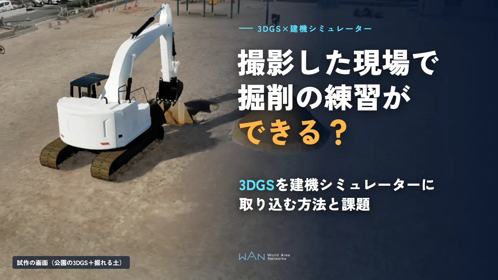
Key points
3DGS scenery alone does not allow excavation practice
3DGS is a collection of particles that records appearance, and it cannot change the shape of the ground. In the prototype, we replaced only a 20 m square digging area with diggable soil simulation.
Build it in three parts: scenery, digging area and seams
We rendered the scenery as 3DGS, hid the ground particles only where the soil was dug, and cast the machine's shadow onto the particles so the boundary cannot be seen from the operator's seat.
Using it in VR requires one more step of lighter rendering
On a monitor, rendering had headroom. In a VR headset, however, it did not reach 72 fps, and the scenery appeared to wobble.
01What Does It Mean to Use 3DGS in a Simulator? How It Differs from Sites Built with 3DCG or Point Clouds
3DGS records a site as a collection of semi-transparent particles that each have a color and a shape. Its strength is that, just by scanning as if taking photos, it reproduces scenery close to what you see, down to building windows, tree leaves and patterns on the ground.
There are other ways to build a simulator training ground besides 3DGS. Each records different things and suits simulators in different ways.
| Method | What it records | Ease of use in a simulator | Weaknesses |
|---|---|---|---|
| 3DCG (built by hand) | The shapes and textures you build | Motion such as digging the ground or colliding with objects can be built freely | The more closely you recreate a real site, the more work it takes |
| Point cloud | Shape (point positions and colors) | Dimensions can be measured | Up close, gaps between points show through, so it hardly looks like scenery |
| Mesh (surfaces built from photos) | Shape and photographic surfaces | Can be used for collision | Fine objects such as trees and thin fences tend to break down |
| 3DGS | Appearance (particle color, shape and opacity) | Scenery close to what you see, down to fine objects | Particle shapes cannot be changed, and there is no collision |
What 3DGS is good at is scenery. What people want to practice in a construction machinery simulator, however, is digging the ground and piling soil. For that reason, in the prototype we divided the site into three parts: scenery, digging area and seams. The scenery is left to 3DGS, only the digging area is replaced with soil simulation, and the boundary between the two is finished so that it cannot be seen.
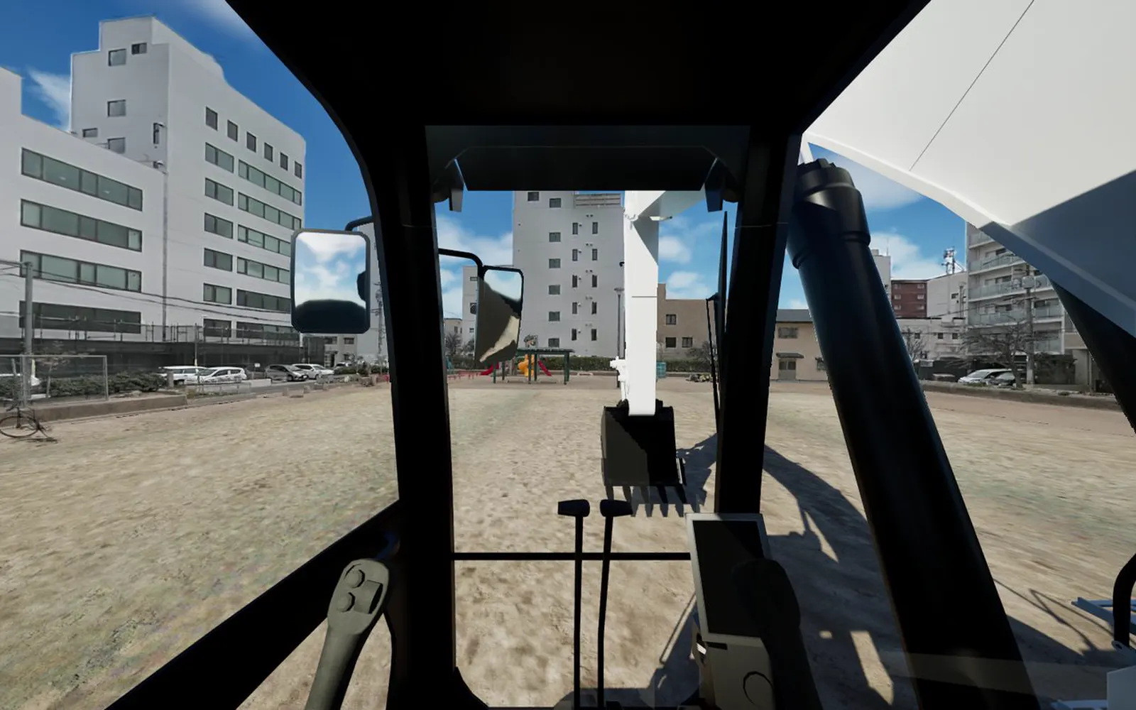
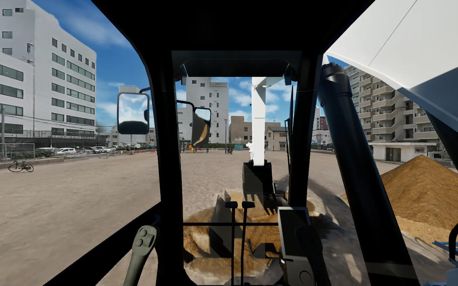
The playground equipment, buildings and trees seen through the cab windows in Figure 1 are all rendered with 3DGS particles.
02Why 3DGS Alone Cannot Be Used for Excavation Practice
Even if you load 3DGS scenery into a simulator as it is, a machine cannot dig the ground. This is because 3DGS is data that records appearance and has no ground "surface".
| Property of 3DGS | Problem in a simulator | How the prototype handled it |
|---|---|---|
| Particle positions and shapes are fixed | The ground does not dent when dug | Replace only the digging area with diggable soil simulation |
| No information about surfaces or thickness | The machine passes through the ground | Estimate ground height from the particles and lay an invisible ground |
| Brightness and shadows are baked into the photos | The machine's shadow does not fall on the scenery | Compute only the machine's shadow and darken the particles |
| The number of particles reaches several million | Rendering becomes heavy | Make versions with fewer particles for each use |
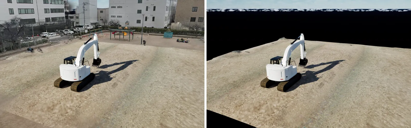
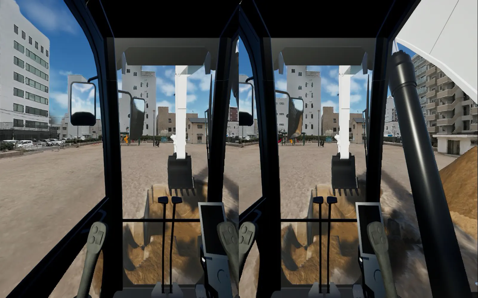
The left side of Figure 2 shows the prototype screen with all of the scenery rendered, and the right side shows the same screen with 3DGS turned off. With 3DGS off, only the diggable soil patch (36 m square) remains. In other words, almost all of the scenery the user sees is 3DGS, and what the machine actually touches is the soil patch at its feet.
03A Prototype That Brought Park 3DGS into a Construction Machinery Simulator
For the prototype, we used data from a park scanned with XGRIDS's handheld scanner "Lixel K1" and turned into 3DGS. It had about 5.54 million particles, and the file (PLY format) was 376 MB. It was loaded into the soil test ground of WAN's construction machinery simulator METATORE.
Scenery: Render the park 3DGS as particles
3DGS is rendered with a mechanism separate from the simulator's 3DCG and overlaid on the screen. Because color grading (tone mapping) changes the photographic colors, we overlaid it on the screen after color grading and compared depths with the machine and ground to decide what is in front and behind. The version for monitors has 2.5 million particles, and the VR version is reduced to 1.5 million. Because particles are thinned out starting from those that appear smallest on screen, from the operator's seat the difference between 1.5 million particles and all particles shows only slightly, in the detail of distant buildings.
Digging area: Turn only a 20 m square of the plaza into soil simulation
The digging area should be a flat place in the plaza with no objects. In the prototype, we prepared a command that, given a 3DGS file and a site name, outputs a top-down map with a recommended area and generates the ground height, soil surface color and particles to render all at once. For this park, one run finished in about one minute.
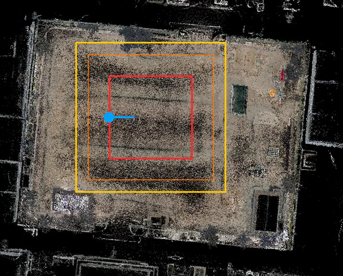
On the surface of the soil patch, we applied the 3DGS colors seen from directly above. Because of this, the patch looks like the same pattern as the surrounding 3DGS ground before it is dug.
Seams: Hide the ground particles only where the soil was dug
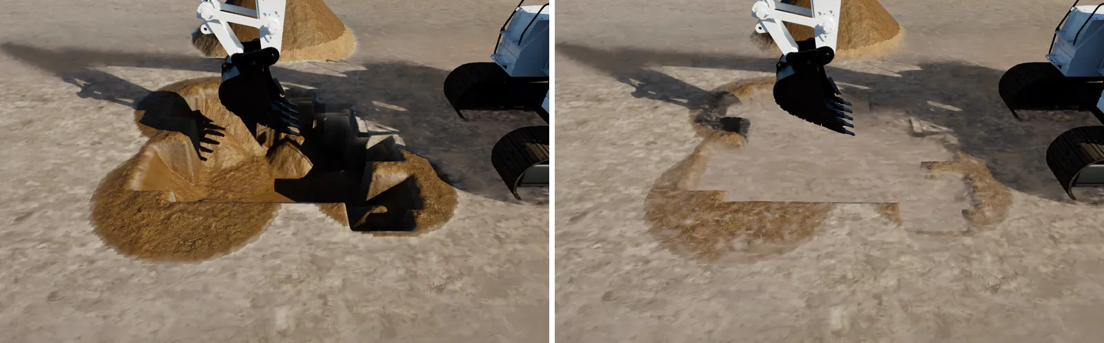
We keep the 3DGS particles on the ground inside the patch as well. Then, only where the soil height has changed by 3 cm or more from the start do we stop drawing the ground particles above it. The left side of Figure 4 shows the screen with this processing: only the hole and the piled soil are visible, and the surroundings remain 3DGS ground. The right side shows the screen without it, where ground particles stay over the hole like a lid.
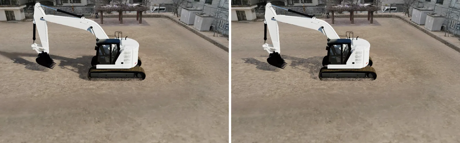
The machine's shadow is also part of the seams. Shadows in 3DGS are baked into the photos, so the shadow of a machine moving in the simulator does not fall on the scenery. We therefore captured a depth image of only the machine from the sun's direction and darkened particles inside the shadow by 45%. In addition, because the soil is lit by computation, it looked 12–15% brighter than the 3DGS ground as it was. After multiplying the soil surface color by 0.87 to match, the edge of the patch can hardly be seen from the height of the operator's seat.
Marketer's note
When scanning a site, attention tends to go to the buildings and facilities you want to show. If you plan to bring the data into a simulator, however, the ground of the plaza where the machine will move is the most important data. If the ground particles are coarse, the color and height of the digging area become coarse too. Decide where the machine will operate before scanning, and walk and capture that ground carefully; it changes how the result looks after import.
04The Rendering Cost of 3DGS Measured in the Prototype
When using 3DGS in a simulator, the concern is rendering cost. In the prototype, we measured GPU time in the same scene with and without 3DGS, and took the difference as the 3DGS share. The conditions were a laptop (GPU: NVIDIA GeForce RTX 5070 Laptop, 8 GB), a 1920×1080 screen, and running in the development editor.
| Number of particles | Time to render 3DGS (operator's seat view) | With the machine's shadow cast |
|---|---|---|
| 1.5 million (VR) | 1.7 ms | 2.3 ms |
| 2.5 million (monitor) | 2.2 ms | 3.0 ms |
| All (5.35 million after import) | 4.6 ms | Not measured |
To run at 60 fps, each frame must fit within about 16.7 ms. With the 2.5-million-particle version, a frame took 13–14 ms (70–75 fps) even with 3DGS added. For training operated on a monitor, adding 3DGS scenery still leaves headroom in rendering. Because particle sorting is done on the GPU, the CPU load has not increased either.
05Four Issues That Remain When Using 3DGS in a Construction Machinery Simulator
While it reached a usable look on a monitor, the prototype also revealed several issues. Each of them is expected to be addressable through how the site is scanned or how rendering is built.
| Issue | What happened in the prototype | Next step |
|---|---|---|
| Rendering cannot keep up in VR | On Meta Quest 3 it ran at 22–35 fps, short of the required 72, and the scenery and dug hole appeared to wobble | Rendering particles at half resolution reduced the 3DGS share for both eyes from 6.7 ms to 2.9 ms (measured with an emulation of both eye screens). Checking on the headset is still to come |
| Ground height is coarse | Because ground height was estimated from 3DGS particles, 2–3 cm of roughness remained | Build ground height from a LiDAR point cloud (such as XGRIDS K2) or a mesh made by the scanning software |
| Light and shadow cannot be moved | Shadows of buildings and trees are baked into the photos and do not match when the simulator's sun is moved | Match the training time of day to the time of scanning |
| Objects in the digging area remain | For trees and benches in the area, only particles up to 3 m above the ground disappear | Choose an open plaza as the area, or handle objects in the area separately |
One cause of the wobble in VR is that when rendering cannot keep up with 72 fps, the headset fills in the missing frames. That makes whether 72 fps can be maintained with 3DGS added the deciding factor for use in VR.
Marketer's note
Whether to train in VR or on a monitor is a point worth deciding first. Even with the same 3DGS, VR renders both eyes at high resolution, so it is several times heavier than a monitor. One approach is to learn the controls on a monitor first and have experienced people finish in VR. If you plan to use VR, preparing a version with fewer particles and lower screen resolution from the start gives peace of mind.
06Talk to WAN About Everything from 3DGS Scanning to Simulator Import
The scenery, digging area and seams described so far are work that spans both scanning and simulator development. WAN handles all of these in-house: 3D scanning with XGRIDS K2, Machica, a viewer for 3DGS in the browser, and METATORE, a construction machinery simulator.
- Scan the scenery: With XGRIDS K2, we create a point cloud and 3DGS in a single scan. The point cloud used for ground height is captured at the same time
- Check the scenery: In Machica, you can look around the 3DGS in the browser before import and check candidate digging areas with stakeholders
- Build the digging area: With METATORE's soil simulation, operators can practice digging and piling
- Finish the seams: We adjust the import mechanism built in this article's prototype to each site's data
Note that 3DGS import is at the prototype stage and is not yet included in the METATORE product. If you would like to try it with data from a real site, please contact us about contract development or joint research.
07Summary: Think of a 3DGS Simulator in Terms of "Scenery, Digging Area and Seams"
3DGS can record a site as scenery close to what you see. That alone, however, does not allow excavation practice. When turning it into a training ground, prepare in these three parts.
Scenery: Scan carefully all the way to the plaza where the machine will move
Scan not only buildings and trees but also the ground where the machine will move, walking over it. If you will use VR, also prepare a version with fewer particles.
Digging area: Choose a flat place with no objects
If there are trees or benches inside the digging area, particles remain. Choose a flat place in the plaza with no objects.
Seams: Match shadows and brightness to the scenery
Hiding particles over dug areas, casting the machine's shadow onto the particles and matching the soil's brightness to the 3DGS ground make the boundary hard to see from the operator's seat.
We recommend deciding three things before proceeding with 3DGS scanning and simulator import: the site to scan, the area where the machine will operate, and the screen used for training (monitor or VR).
Sources and references
Bernhard Kerbl et al., "3D Gaussian Splatting for Real-Time Radiance Field Rendering," ACM Transactions on Graphics 42(4) (SIGGRAPH 2023) https://repo-sam.inria.fr/fungraph/3d-gaussian-splatting/ (accessed November 13, 2026)
XGRIDS, "Lixel K1" product page https://www.xgrids.com/intl/lixelk1 (accessed November 13, 2026)
Figures 1–7: Screens from WAN's prototype (captured November 2026)
Consultation
3DGS scanning and simulator development
From 3D scanning with XGRIDS K2 to sharing 3DGS and importing it into a construction machinery simulator, you can consult one team. We also welcome prototypes and joint research using data from real sites.